Arduino 專案 - 以電視遙控器控臥室天花板電燈開關 (2) : Arduino Project - Switch Bedroom Light with TV remote Part 2
上次完成 Arduino 用TV搖控器來開關燈 開發原型後,一直到今天才把它完全的做在一個麵包板上。由於是電子相關的新手,真是花了很多功夫才完成。在過程中,我還把正負極裝反,害我以為 Arduino mini pro 被我燒毀了! 找了好久,還好我有發現這個問題,不然,你也看不到這個例子了!
After I completed Remote control light switch with Arduino and TV remote project last time, I was looking for ways to move all components on to a perfboard and ready for a permanent setup. Due to I am really new to electronics, it took me a lot of time to get the job done. During the process, I accidentally soldered the power source positive to negative and negative to positive. I was panic and, for once, I thought I had burned the Arduino mini pro. I was happy that I found the problem and solved it after few hours...
對沒學過焊接的新手,把零件焊到電路板上,真的是很不容易!! 看我焊的跟狗啃的沒兩樣。
For a newbie like me whom never learn how to solder, soldering components to the perfboard is really challenging!
我到電子零件店買了這個編號 KT-8 的電路板。
使用長的接腳,拿它來當固定 Arduino mini pro 的工具。
I bought this perfboard coded "KT-8" in an electronic component shop and it only cost NT$10.
With the long connection pins, I utilized them to fix Arduino mini pro in place on the perfboard.
一開始先選定這個角落當作 Arduino mini pro 固定位置,要記得把五個 pin 腳朝外,這樣要上傳程式比較方便。
Pick up the corner of the KT-8 perfboard as the fix position. Don't forget to face the five pins towards outside of the KD-8 for easier connection to the USB uploader later.
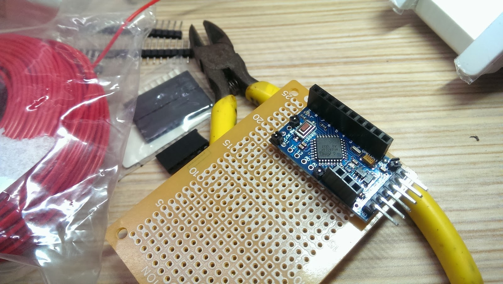
我不想一開始就把 Arduino mini pro 的腳位焊死,這樣我可以較彈性的應用,所以也買了底下這樣的接口,所以我可以任意調動我要用的 pin 。我只有把大概用的到的腳位加上接口,其它的就留著作為固定的用途。
I picked up the connection pins as shown below to solder them on the side of Arduino mini pro, so I could have the flexibility to change connection to the pins later in the project. As you can see, I saved couple of empty spots on the Arduino mini pro, so I could use them to fix it to the perfboard later.

找四個留下的空 pin 腳,焊上排針來支撐 Arduino mini pro。我把排針剪下一支一支的共四支,等一會再把這四個排針焊到麵包板上。
Decided four empty spots and used the connection headers came with Arduino mini pro and soldered them together. Later, these connection headers would become the supporting material on the perfboard for Arduino mini pro. The connection headers are in a row of 20, so I cut down a single header totaling 4 of them and make them into supporting materials.

我的工作桌...
My soldering table...


 Photos of soldering work here:
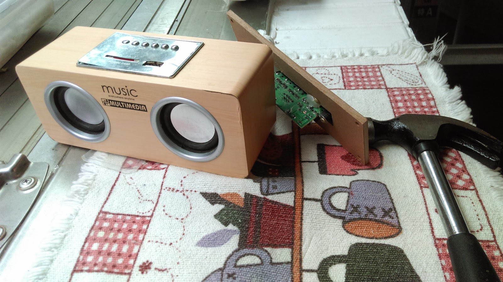
因為繼電器模組上有一個洞,所以我先用電鑽在電路板挖個洞,再用螺絲把它鎖住。
但固定單邊不夠勞固,所以我又用一條束帶把繼電器模組緊緊的繫在電路板上。
Drilled a hole on the perfboard, and took a screw to fix the relay module on the perfboard. However, fixed on one side is not enough, so I took a cable tight to keep the relay module tightly on the perfboard.

Photos of entire board here:
我刻意把紅外線接收器的線做長一點,想說把它延伸到天花板燈的外緣,這樣遙控訊號才不會被我燈上的裝飾玻璃給擋住。結果測試後發現這根本不需要,因為紅外線接收訊號功能很強,我試著隔著 Macbook Air 的螢幕,居然還可以接收的到!
I intended to make the IR receiver wire extra longer, so I could extend the IR receiver outside the bed room light or it might be obscured by the decorative glasses. After few tests, I found out the IR receiver could even receive the TV remote signal even I intended put it behind my Macbook Air display!
看一下這兩周以來的成果如下,接下來要為它接上電源及安裝到天花板上,才算真正的完成。
After two weeks of hard working, here is the project I had so far. Next time, I will need to find a 5V power source for the perfboard and think how to place it into bed room light.
Video of the working project on perfboard.
After I completed Remote control light switch with Arduino and TV remote project last time, I was looking for ways to move all components on to a perfboard and ready for a permanent setup. Due to I am really new to electronics, it took me a lot of time to get the job done. During the process, I accidentally soldered the power source positive to negative and negative to positive. I was panic and, for once, I thought I had burned the Arduino mini pro. I was happy that I found the problem and solved it after few hours...
對沒學過焊接的新手,把零件焊到電路板上,真的是很不容易!! 看我焊的跟狗啃的沒兩樣。
For a newbie like me whom never learn how to solder, soldering components to the perfboard is really challenging!
我到電子零件店買了這個編號 KT-8 的電路板。
使用長的接腳,拿它來當固定 Arduino mini pro 的工具。
I bought this perfboard coded "KT-8" in an electronic component shop and it only cost NT$10.
With the long connection pins, I utilized them to fix Arduino mini pro in place on the perfboard.
一開始先選定這個角落當作 Arduino mini pro 固定位置,要記得把五個 pin 腳朝外,這樣要上傳程式比較方便。
Pick up the corner of the KT-8 perfboard as the fix position. Don't forget to face the five pins towards outside of the KD-8 for easier connection to the USB uploader later.

我不想一開始就把 Arduino mini pro 的腳位焊死,這樣我可以較彈性的應用,所以也買了底下這樣的接口,所以我可以任意調動我要用的 pin 。我只有把大概用的到的腳位加上接口,其它的就留著作為固定的用途。
I picked up the connection pins as shown below to solder them on the side of Arduino mini pro, so I could have the flexibility to change connection to the pins later in the project. As you can see, I saved couple of empty spots on the Arduino mini pro, so I could use them to fix it to the perfboard later.

找四個留下的空 pin 腳,焊上排針來支撐 Arduino mini pro。我把排針剪下一支一支的共四支,等一會再把這四個排針焊到麵包板上。
Decided four empty spots and used the connection headers came with Arduino mini pro and soldered them together. Later, these connection headers would become the supporting material on the perfboard for Arduino mini pro. The connection headers are in a row of 20, so I cut down a single header totaling 4 of them and make them into supporting materials.

Photo above: Long connection pins for fixing Arduino mini pro in place on the perfboard.
My soldering table...

固定 Arduino mini pro 後,焊上 LED,電阻,再接上線路,記得先測試一下。
我在這裡測試時,發現它不會動,花了好久時間才發現是正負接反了!
After fixed Arduino mini pro in position, solder RGB LED, resistors, and wires.
Remember to test the whole setup before move forward.


因為繼電器模組上有一個洞,所以我先用電鑽在電路板挖個洞,再用螺絲把它鎖住。
但固定單邊不夠勞固,所以我又用一條束帶把繼電器模組緊緊的繫在電路板上。
Drilled a hole on the perfboard, and took a screw to fix the relay module on the perfboard. However, fixed on one side is not enough, so I took a cable tight to keep the relay module tightly on the perfboard.

Photos of entire board here:
我刻意把紅外線接收器的線做長一點,想說把它延伸到天花板燈的外緣,這樣遙控訊號才不會被我燈上的裝飾玻璃給擋住。結果測試後發現這根本不需要,因為紅外線接收訊號功能很強,我試著隔著 Macbook Air 的螢幕,居然還可以接收的到!
I intended to make the IR receiver wire extra longer, so I could extend the IR receiver outside the bed room light or it might be obscured by the decorative glasses. After few tests, I found out the IR receiver could even receive the TV remote signal even I intended put it behind my Macbook Air display!
看一下這兩周以來的成果如下,接下來要為它接上電源及安裝到天花板上,才算真正的完成。
After two weeks of hard working, here is the project I had so far. Next time, I will need to find a 5V power source for the perfboard and think how to place it into bed room light.
Video of the working project on perfboard.


Comments
Post a Comment